Friday 28 November 2008

Unconventional Antennas from NASA Labs

Yes, I know I'm writing a lot about NASA, the Jet Propulsion Labs, and space stuff in general. This interests me a lot, anything to do with space travel and its related technology. I still remember watching the historic moon land in 1969 on our first Zenith colour TV. You've probably noticed too that I like working with different antenna technologies.

I ran across a NASA article that describes their antenna design software. It's nothing like what's available to the ham community. Their software takes ten hours to design new antennas for their satellites and spacecraft. You can imagine the criteria as to size, weight, and performance required for operation in deep space.

Here's what their computer clusters have managed to design - very unconventional - it looks like a bent paper clip but their computers have determined this is the best performing hardware for their satellites.


NASA describes their software, that runs on a network of personal computers as "evolutionary". The above photo shows an antenna that can fit into a one-inch space (2.5 by 2.5 centimeters) in front of 'borg' of computers.

"The AI software examined millions of potential antenna designs before settling on a final one," said project lead Jason Lohn, a scientist at NASA's Ames Research Center, located in California's Silicon Valley. "Through a process patterned after Darwin's 'survival of the fittest,' the strongest designs survive and the less capable do not."

The software started with random antenna designs and through the evolutionary process, refined them. The computer system took about 10 hours to complete the initial antenna design process. "We told the computer program what performance the antenna should have, and the computer simulated evolution, keeping the best antenna designs that approached what we asked for. Eventually, it zeroed in on something that met the desired specifications for the mission," Lohn said.

When I visited the JPL in Pasadena California in April of this year I discovered a group of hams working there and they had a JPL ham club and repeater. Bets that some hams had a hand in this software. Now if they could only release the software to us lowly hams who use wire antennas and minimalist stealth antennas. I need something this small on 160 meters.

NASA 'EVOLUTIONARY' SOFTWARE AUTOMATICALLY DESIGNS ANTENNA

JPL Amateur Radio Club

(Photos courtesy of NASA Ames)

Monday 24 November 2008

NASA Tests First Deep-Space Internet

NASA Jet Propulsion Laboratory (11/18/08)


Some exciting new communication technologies are sure to emerge from these new protocols - they may even trickle down to amateur digital modes.


NASA Jet Propulsion Laboratory (JPL) engineers have successfully tested the first deep space communications network based on the Internet, using the Disruption-Tolerant Networking (DTN) protocol to transmit dozens of images to and from a spacecraft more than 20 million miles from Earth. NASA and Google's Vint Cerf jointly developed the DTN protocol, which replaces the Internet's TCP/IP protocol for managing data transmissions. "This is the first step in creating a totally new space communications capability, an interplanetary Internet," says NASA's Adrian Hooke. An interplanetary Internet needs to be strong enough to withstand delays, disruptions, and lost connections that space can cause. For example, errors can happen when a spacecraft slips behind a planet, or when solar storms or long communication delays occur. Even traveling at the speed of light, communications sent between Mars and Earth take between three-and-a-half minutes to 20 minutes. Unlike TCP/IP, DTN does not assume there will be a constant end-to-end connection. DTN is designed so that if a destination path cannot be found, the data packets are not discarded but are kept in a network node until it can safely communicate with another node. In October, engineers started a month-long series of demonstrations, with data being transmitted using NASA's Deep Space Network twice a week.


Researchers say the interplanetary Internet could allow for new types of complex space missions that involve multiple landed, mobile, and orbiting spacecraft, as well as ensure reliable communications for astronauts on the surface of the moon.

NASA Tests First Deep-Space Internet

(photos were taken at the NASA JPL in Pasadena California, during my visit there in April 2008)

30 Meter Weekend

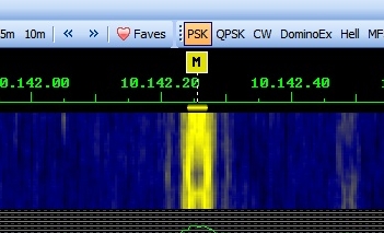
30 meters was very busy this weekend but I didn't get to operate very much due to a GTD (getting things done) list. The little time I did have to operate worked out quite well. I tried my hand at Olivia mode. I had just finished reading in the December08 QST about this magic mode and made a nice contact to W9NWR down in Wisconsin. Copy was excellent and it's expected of this mode. Though Chuck's signal was full copy with Digital Master 780 he wasn't moving the S meter. Olivia presented perfect copy with no effort on my part. I had the pre-amps off in the FT-950 and about -6dB of attenuation - just enough to lower the band noise. I like Olivia but it is a really slow mode of communications. I can see using it under extreme band conditions where noise is bad or the signals are not visible in the waterfall. At least I could keep the buffer full with my typing.

The next morning I snagged some good DX just before heading out for a Sunday filled with activities. ES0IC, Meeme, on the island of Kassari (IOTA-EU034) in Estonia on PSK31. He was 599 copy on my PAR EF-30 end fed dipole. A really nice contact and great DX to boot. I noticed many DX stations operating Sunday morning. Sunday night was good too and the band stayed open well past 10:30pm local time. A strong Puerto Rican station, WP3UX, was calling CQ for at least a couple of hours. On Saturday night the band closed just after sunset.

If you haven't tried 30 meters give it a go. It's a great DX band, only digital and CW modes are permitted (no contests!), and if you hit it right there's a lot of great DX to be had. All contacts on the weekend were completed using 20 watts output and using my FT-950. The 950 dsp filtering options are great for digital work.

To keep tabs on 30 meter DX activity I was using a new DX cluster called DXAnywhere programmed by a young British chap, Peter, M3PHP. Peter says, "The system also includes a full blown social networking system where users can setup profiles of themselves and their amateur radio background and become friends with other users! We're also keen on keeping the system fresh so on a monthly basis we're going to be adding new applications into the mix."

Friday 21 November 2008

30 Meter Digital Group 1 Year Anniversary Weekend


For all of you digital mode enthusiasts this is the perfect weekend for testing those 30 meter antennas and setting the bandswitch to 30 meter position.

The 30 Meter Digital Group is celebrating their one year anniversary this weekend. The activity starts this weekend November 22nd and 23rd.

10.140 USB +/- 1000 PSK

(10.132 – 10.145 – HELL, OLIVIA, MFSK, RTTY, WSPR, PropNet, Etc)

10.140 +2000 – 30MDG Members Dedicated Hours from 1900z to 2200z - 30MDG members look for other members to ragchew with further up the waterfall.

Let's celebrate our 30MDG 1st year anniversary and have some fun on the 30 Meter Band! The 30 Meter Digital Group would like to invite our 1,350 plus members along with any and all digital operators for a casual digital weekend on the 30 Meter Band.

Those that are 30MDG members this would be a good time to mark your calendar and meet up with other 30MDG Members for a ragchew or meet a DX member. You do NOT have to be a 30MDG member nor join the 30MDG to participate; just get on the 30m band and have some digital fun!

Our 30 Meter Digital Group promotes:

- Awareness of the unique 30 Meter Band (note: we are SECONDARY USERS
of this band and must give way to Primary users so please use good operating procedures)

- Proper digital mode operation and procedures

- Experimenting with different digital modes, power, antennas, etc.

- Low power operation and only using the least amount of power needed for the contact at hand (note: 75% of digital mode operators use between 20-40w on the band…also note for U.S.A. operators the 30m band is a great place because we must use <200w so we are all on the same playing field on the 30 meter band…oh yes, no voice for U.S.A. ops so it is really an all digital band)

- Casual operating on the 30 Meter Band from ragchews to DX but we do NOT promote Contesting….30 Meters is a WARC band and one place we all can enjoy away from contesting.

- Increase 30 Meter digital mode use on this under used unique band that has the best of both 20 Meter and 40 Meter propagation because it sits between them (again note we are SECONDARY USERS)

Here at VE3MPG I use the PAR EF-30 End Fed Dipole on 30 meters. I'll report after the weekend on conditions and activities.

Yahoo 30 Meter PSK Group

30 Meter Digital Group

30 Meter Antennas

Arnie Coro CO2KK talks about 30 meters

Wednesday 19 November 2008

VE3MPG, Cyborg and Bionic Ham

Cyborg is a fictional character, a superhero appearing in comic books published by DC Comics. Ooops wrong definition; here we go again - Cyborg: A cyborg is a cybernetic organism (i.e., an organism that has both artificial and natural systems). The term was coined in 1960 when Manfred Clynes and Nathan Kline used it in an article about the advantages of self-regulating human-machine systems in outer space. That's close enough, though I haven't been to outer space yet but it could happen. And, I'm not a superhero or even a superham.

In the fall of 2006 I received a cochlear implant, my bionic implant.

In the mid 1980s I was losing my hearing at a rapid pace due to a genetic fault. Many in my family were hard of hearing and the older family members, my father and my grandmother were left with little hearing. By 1990 I was wearing two intra canal digital aids but speech and going to the movies and TV were extremely difficult to hear. By 1993 I was profoundly deaf and could barely use a phone and had a closed captioning device on my TV set. I was wearing very powerful behind the ear aids at that time and by the year 2000 I was really struggling. I had my first appointment at the Audiology Unit at Ottawa's Civic Hospital but didn't qualify for an implant at that time. Apparently I wasn't deaf enough yet. Criteria has since changed making it much easier to qualify for a cochlear implant.

Deaf or hard of hearing persons learn to cope with their disability and I learned to lip read very well. Of course lip reading only worked if the other person was facing me. I carried on pretty well in this way for a few years. In 2005 while at home my burglar alarm tripped and two squad cars showed up - I live out in the country but it didn't take long for the police to respond. I signed to them that I was deaf and they wondered if I could hear the alarm and I shook my head 'no'. Well that was the turning point for me - I could no longer use a telephone but did rely on the very early Blackberries for text and email messaging - another way of coping.

So I got with the program again at the Civic hospital after an audiologist at the Canadian Hearing Society recommended it since hearing aids couldn't do anything more for me.

Curtail my ham activities it did. In 1993 I got so discouraged I sold my HF gear, a beautiful Kenwood TS-520SE as I couldn't hear SSB anymore. CW was fine even up to my last few days before the implant. With the little residual hearing I had left I was still able to hear that CW tone. I hadn't done 2 meters from the car for years but still had a radio installed just in case. I remember the day I just couldn't struggle anymore not hearing the guys on the repeater. I really missed that.


Pictured above is the implant receiver, the Advanced Bionics HiRes 90k the most advanced DSP based processor available. The gold plated titanium part is the enclosure for the electronics. The clear part with gold wires running along the perimeter is the implant antenna with a small magnet in the center. The long sensor array tip is wound inside the cochlea of the inner ear. There are 16 sensors on the tip and most of them end up touching ever so slightly some of the nerves inside the damaged cochlea. A small channel is routed out from the surface of the skull just above and behind the ear to seat the processor and antenna. A hole is then drilled through the mastoid bone behind the ear to carefully insert and position the sensor array in the cochlea. Some extremely small metal guide tools are used by the surgeon to carefully insert the array without doing any damage to the fragile cochlea.

This photo shows a channel routed from the skull - where the receiver will reside. You can see the sutures that will hold the receiver in place and the electrode lead channel. The skin and scalp are then replaced and sutured back. I arrived at the Civic Hospital in the morning and was prepped for surgery. After 5.5 hours in the OR I was wheeled into recovery, then ICU and was released at 6a.m. the next morning. Five weeks later my implant was activated.

Did deafness affect my ham radio hobby? Yes it did. Did I give up? No!

Helen Keller said that if she had to choose between being deaf and being blind, she'd be blind, because while blindness cut her off from things, deafness cut her off from people.

My hearing today is based on the skills of the engineers, programmers and researchers at Advanced Bionics in California. Sound is coded in bits and bytes and transformed into something recognizable to my brain. My implant has 16 electrodes, but the virtual-channels software will make my hardware act like there are actually 121. Manipulating the flow of electricity to target neurons between each electrode creates the illusion of seven new electrodes between each actual pair, similar to the way an audio engineer can make a sound appear to emanate from between two speakers. It takes at least 100 channels to create good music perception.

The photo above is me, five weeks after surgery and the day of my 'activation'. This is the external processor with a small T-mic in the ear where the sound is picked up. The gray headpiece is held on with a small magnet where the internal receiver, antenna and magnet are located. A battery located on the external processor powers the internal electronics through the skin. A diagnostic light on the external processor stops blinking when a data link is established with the internal processor. I'm being programmed via that cable to an XP computer running Advanced Bionics' mapping software. Three new strategies can be programmed to the external processor - I have one for loud environments, very quiet environments and one for regular sound environments. The T-mic detaches and I can plug my Ipod directly to my implant for listening to music (mono only!) or podcasts which I download to the Ipod Touch.

I am slowly making more voice contacts on SSB and FM but still have a lot of difficulty with bad audio on the phone bands. Some operators have excellent audio while many have overprocessed and overdriven audio. I find this especially on the local HF nets where good net etiquette is not followed. The net controls either speak too fast or you get the 'yellers' with their mic gain turned up too high. It will just take time and the patience of the hams at the other end of the mic. Today most of my HF activity centers on the digital modes and I enjoy that immensly.

If any of you have questions about this article please post them in the comments section or email me directly via the QRZ.com listing for my call.

Sunday 16 November 2008

17 Meters and K4CMC

17 meters has been open for most of the morning to Europe and now the southern U.S. states are rolling in. QSB is heavy but signals are 20+ S9 most of the time. I worked Bruce Davis, K4CMC. He used to work at NASA during the Apollo moon missions. Small world after posting the article about the recovered moon photos yesterday.

Here's a picture of Bruce in the Apollo 11 cockpit at Kennedy Space Center in July of
1969 about one week prior to the first lunar landing mission.


Bruce says, "After getting out of the USAF I worked as an Instrumentation Technician and then as a Senior Apollo Spacecraft Electronic Technician at Kennedy Space Center from 1965-1970 as a Spacecraft Operator (SCO) in cockpit of Apollo Spacecraft during ground testing on many of the Apollo missions,including Apollo 11 and Apollo 13."

This is the coolness factor of amateur radio. You really never know who you are going to meet on the air. I always make it a habit to check QRZ.com for profiles of the hams I meet on the bands.

Saturday 15 November 2008

New Pictures of the Moon Discovered

A woman saves the 1960s photo archives of the moon's surface


This article really is about ham radio - well more specifically how collecting and hoarding our treasures can really pay off. The absolutely cool technical stuff going on here is historical, especially with the 40th anniversary of the moon landing taking place next year on July 20th 2009.

A retired NASA employee, Nancy Evans, kept many things in her garage. But as time passed, NASA forgot. In fact, it would have thrown the machines out, if not for Nancy Evans, who had worked the project. She stored the machines in her garage for more than 20 years, and when NASA wanted to recycle the moon tapes, she took those, too.

"I had spent most of my working life saving data, and salvaging data, seeing that it got put safely in the planetary data system. I wasn't about to let this huge data set be thrown away," said Nancy Evans, a former NASA/JPL researcher.

In the late 1960s, NASA sent five Lunar Orbiter missions to photograph the surface of the moon and gain a better understanding of the lunar environment in advance of the Apollo program. Data were recorded on large magnetic tapes and transferred to photographic film for scientific analysis. When these images were first retrieved from lunar orbit, only a portion of their true resolution was available because of the limited technology available.

The Lunar Orbiter Image Recovery Project, located at NASA's Ames Research Center at Moffett Field, Calif., is taking analog data from original recorders used to store on tape and 1,500 of the original tapes, converting the data into digital form, and reconstructing the images. The restored image released Thursday confirms data from the original tapes can be retrieved from the newly-restored tape drives from the 1960s when combined with software from 2008.

"I'm glad that we could offer our services to the project team and play a part in the recovery of such an historic image of the moon," said Ames Director S. Pete Worden.

Future images will be made publicly available when they are fully processed and calibrated. The intent of this project is to facilitate, wherever possible, the broadest dissemination and public use of these images.

"It's a tremendous feeling to restore a 40-year-old image and know it can be useful to future explorers," said Gregory Schmidt, deputy director of the NASA Lunar Science Institute at Ames. "Now that we've demonstrated the capability to retrieve images, our goal is to complete the tape drives' restoration and move toward retrieving all of the images on the remaining tapes," he added.

Another, image of the lunar surface now shows details as small as one meter, which they can compare with future mapping missions.

"This is going to show us how the moon is changing. We fully expecting to see some new craters," said Greg Schmidt, Deputy Director of Lunar Sciences.

A classic case of pulling treasure from what might have been in the trash and all because Nancy Evans was a bit of a packrat.

As the images are processed, they will be submitted to the Planetary Data System, which NASA's Space Science Mission Directorate in Washington sponsors in cooperation with NASA's Jet Propulsion Laboratory in Pasadena, Calif. The images also will be calibrated with standard mapping coordinates from the U.S. Geological Survey's Astrogeology Research Program in Flagstaff, Ariz.

NASA will launch the Lunar Reconnaissance Orbiter in 2009 to map the moon's surface. The restoration of the Lunar Orbiter images to high quality images will provide the scientific community with a baseline to measure and understand changes that have occurred on the moon since the 1960s. These data could help mission planners assess the long-term risk to lunar inhabitants from small meteor impacts and establish longitude and latitude lines for lunar mapping.

"This effort was made possible by the vision and dedication of Apollo-era NASA employees, independent researchers, and a true veteran team of engineers and young students," said Dennis Wingo, the program lead for the project.

"We liken it to archeology. Techno-archeology," said Dennis Wingo, an imaging expert.

NASA's Exploration Systems Mission Directorate and Innovative Partnerships Program Office in Washington provided initial funding for the project. Engineering and logistics for the project team were provided by Wingo of SkyCorp, Inc., Huntsville, Ala., with donated services by Keith Cowing from SpaceRef Interactive, Inc., Reston, Va., under the auspices of Alliance of Commercial Enterprises and Education for Space, and the NASA Lunar Science Institute.

To view the image and for more information about the Lunar Orbiter Image Recovery Project, visit:

http://www.nasa.gov/topics/moonmars/features/LOIRP

and

http://www.moonviews.com

For more information about NASA's exploration program, visit:

http://www.nasa.gov/exploration

Download video about the LOIRP project.

Thanks to NASA Ames, JPL in Pasedena and ABC News (KG0-TV, San Fransisco)

Thursday 13 November 2008

40 meter DX via RTTY


Worked OX3DB in Igaliko Greenland on 40 meters RTTY this afternoon at 2030Z. That's a good hour before dusk here south of Ottawa. Conditions are very good around that time. Jan, OX3DB, gave me a 599 signal report. I was transmitting on the PAR EF-40 end fed dipole with 20 watts.

Here's a bit about Igaliko, from the Greenland tourism bureau -

Igaliko is a settlement in the ancient see of Gardar. From the slopes above it, people enjoy the most beautiful and peaceful panorama of the country. The name Igaliko means “The Abandoned Fireplace”. The Norwegian Anders Olsen started farming at Gardar in 1780 and dedicated the place to St. Nicolas, the protector of seafaring people. A ruin of a cross church, 27x16 m, built of sandstone in the 12th century remains there. The ruins of the bishopric cover an extended area, among them the ruins of a 130 m² celebration hall, a tithe-hut, where the tithes were kept, and a cow shed for 100 heads of cattle.

The most remote abode of the pope’s representatives was at Gardar. Exploration voyages to Markland (Labrador and Newfoundland) and voyages for walrus hunting started from there and Brattahlid. Under the choir of the church, skulls of walruses were excavated. Probably people hoped to improve the walrus hunting by burying them near the graves of the chieftains. Gardar was the main centre of education and administration in Greenland.

And a bit more info on Gardar from Wikipedia -

Gardar was the 'capital' of the Norse settlements in Greenland and seat of the bishop of Greenland. Presently the settlement of Igaliku is situated on the same location.

Many ruins of the Norse settlements can still be seen in Igaliku today. The main ruin is of the Gardar Cathedral, a cross-shaped church built of sandstone in the 12th century. The maximum length is 27 m, the width 16 m. Besides the cathedral ruins of the stables (with place for 60 cows) and other buildings can still be seen. Its population in 2005 was 60.
It's interesting to check qrz.com for information about the DX station one works. Sometimes it's a great lesson in geography and history as is the case here with OX3DB.

The last time I worked Greenland was in the very early 80s using the RS satellites and CW using 10 meters up and 144Mhz downlink using a Sinclair ZX-81 for tracking. Printouts were on thermal paper and the tracking program was loaded from a cassette tape player and the Keplerian elements input manually. I believe the Keps in those days were published via the local packet working group bbs.

Amateur Radio Exam Generator

The website of the Canadian regulator, Industry Canada, provides a free download of software to generate Amateur Radio exams. This service is provided as a learning aid for prospective amateurs and as an administrative tool for accredited examiners.The software can be downloaded from "Software to Generate Amateur Examinations".


This software package can produce a unique examination for either a basic or advanced amateur certificate according to the random selection criteria outlined in RIC-3. It will also generate a worksheet, and it has an additional feature that allows self-testing on a home computer.

Wednesday 12 November 2008

Awh Master Commander: Software Control For The YAESU FT 2000 or FT 950

N.B.: September 28, 2015 – From Rick IW1AWH -Due to several reason (personal problems and lack of interest about this utility from the ham community), I'm planning to phase out Master Commander soon. I'll release as an unsupported alpha release the latest build of mc 008 and then the development will be closed.
Many thanks to everyone. Rick.http://iw1awh.jimdo.com/

N.B.: April 26, 2013. This is NOT my software readers! I did not write this and only reviewed it here and as far as I know it is no longer supported or being developed. See the above note for Rick’s information. If you have questions please don’t leave a comment here as I can not possibly respond as I’m not the author or developer.
AWH Master Commander is control software for the Yaesu FT-2000 and the FT-950. What makes this suite of software different from Ham Radio Deluxe and other software for rig control is that each module shows a graphical representation of specific controls of each radio.

Here's an example of the connect screen for the FT-950.


This next control screen is the most impressive - a panoramic display in real time.


This next control component is the transmit equalizer and processor control screen.


Here's the 10 meter FM control module - with tone access control


And finally the SWR control and testing module - be careful of this one as it will sweep the entire band to map the SWR of your antenna. It will also check a band segment or single frequency.


This cutting edge software developed by Rick (Riccardo) Bertoli IW1AWH is in its current beta stage but I can tell you once you try it you'll be hooked. Awh Commander is turning out to be a very comprehensive piece of software to extend the controls of the FT-950 or the FT-2000 to your home computer or laptop. All that's needed is a serial cable connected from your laptop or shack computer to the FT-950 or the FT-2000.

I highly recommend the software and I'm looking forward to what Rick will be doing to further enhance Awh Commander. Rick gives SDR a whole new meaning with this fantastic piece of software.

You can download the beta version from Rick's blog here or go to the site of W4LGH in the U.S.

Cycle 24 Sunspot 1008


A new sunspot (1008) emerged this week signaling more Cycle 24 activity. The bands have been very good even up to 17 meters. PSK stations populate 18.100 and some good DX is to be had.


Above: New-cycle sunspot group 1007 emerges on Halloween and marches across the face of the sun over a four-day period in early November 2008. Credit: the Solar and Heliospheric Observatory (SOHO).

On Nov. 3rd and again on Nov. 4th, double-oh seven unleashed a series of B-class solar flares. Although B-flares are considered minor, the explosions made themselves felt on Earth. X-rays bathed the dayside of our planet and sent waves of ionization rippling through the atmosphere over Europe. Hams monitoring VLF radio beacons noticed strange "fades" and "surges" caused by the sudden ionospheric disturbances.

Good news for the upcoming winter season and should give us some decent conditions for working lots of DX.

I notice that an hour prior to sunset on 40 meters the Europeans start to roll in very nicely. Good signal strengths and many psk stations on. I work psk stations exclusively here and I'll write a future blog posting on that very soon. Well after dark 20 meters is still open with south American stations populating the band.

Coming up on November 22nd and 23rd is the "30 Meter Digital Group 1 Year Anniversary Weekend."

10.140  USB +/- 1000 PSK
(10.132 – 10.145 – HELL, OLIVIA, MFSK, RTTY, WSPR, PropNet, Etc)
 
10.140 +2000 – 30MDG Members Dedicated Hours from 1900z to 2200z
(30MDG members look for other members to ragchew with further up the waterfall)
 
Check into the 30 Meter Feld Hell Net:
30 Meter Net 0000 Z Monday 10.138. Feld Hell Net Control is W8LEW Lew.

Not sure what 30 Meters has to offer? Then go here:
http://www.30meterdigital.org/files/30_Meter_Band_INFORMATION.pdf

30 Meter Digital Group
 

Tuesday 4 November 2008

FT-950 Back On The Air


It's been a few months since I've fired up the FT-950. Got it dusted off and moved back to the shack. The last time it was used was at the MARG Field Day at the Long Island Marina in Kars. It's hard to forget how great the receiver is in the 950.

Late this afternoon I worked TK5IH in Corsica and ZP8AE in Paraguay, on PSK, with 589 and 599 reports using 20 watts to the Cushcraft R6000. Earlier in the day using the 'old' FT-100, I worked Maria, SA2YLM on 20 meters. 17 meters opened just after lunch for a short time and managed to snag a few Europeans with great 5NN reports.

The nice 'width' feature of the FT-950 allows me to narrow down the passband and get rid of high powered stations close to the DX that I want to work. The HRD* waterfall below shows the passband with many signals.


The HRD* waterfall below shows no signals, on either side of the received psk track. This eliminates desensing of the receiver by narrowing the passband so strong signals on either side of the track being decoded dissapear. The FT-950 can also notch out a signal on either side of the decoded signal.


I use Ham Radio Deluxe as control software and Digital Master 780 for digital modes. I find it is one of the most intuitive ham software suites. It keeps track of my logs and can be used for just about any digital mode now current on the amateur bands. There's an excellent satellite tracking module included. Simon Brown, HB9DRV, is continually adding features and tweaking the software. The Ham Radio Deluxe forums are a repository of information pertaining to any subject about digital modes and how to connect Yaesu, Icom, Kenwood, and just about any transceiver to sound card interfaces and to your shack computer. HRD works with Windows XP and Windows Vista.

Some PSK tips:
In PSK modes use UPPER CASE characters sparingly. Lower case text in PSK31 varicode transmits fewer bits of data. You'll increase transmit speed and improve the likelihood of proper decoding on the other end by using lower case text as much as possible. (For example, the difference between a lowercase “e” (11) and an uppercase “E” (1110111) is three times more bits.)

*Ham Radio Deluxe

Monday 3 November 2008

The R6000 Rocks!

Finally got the antenna connected late this afternoon and got on 20 meters, PSK. Worked Florida and Cuba with about 15 watts to the antenna. 599+ reports so I could lower the power a bit more. I’m a bit hesitant to do this as I’m feeding it will el cheapo RG58 coax; about 110 feet of it so the attenuation is about 3.5db. Have to get some connectors on the good RG213 stuff that I have still coiled, new, in the basement.   spots2

Conditions seem to be very good as most signals are way over S9. There’s been some very recent sunspot activity. My favourite site for checking solar activity belongs to Kevin, VE3EN, down in Cornwall Ontario. There’s been a good bit of traffic in the forums these last few days. Check it out.

SOLARCYCLE24.COM

Technorati Tags: ,,

Sunday 2 November 2008

R6000 Up and Running

20081102-IMG_1989 Spent a few hours yesterday getting the 20 foot R6000 set up – it worked right away and tuned very nicely on all of the band portions that I use. I used guy ropes to steady this vertical. In previous years at this location the winds are brutal and the R6000 used to sway precipitously. I am positive this had much to do with weakening the joints and accelerated wear and tear. It’s so windy in these parts that one farm a few lines down from us uses wind turbines and some solar panels for their only power source. Testing the antenna with my MFJ-259 analyzer shows it’s right on the frequencies that I measured for in the instructions.20081102-IMG_1994

The above photo shows the fibreglass repair to the main insulator – this was all shredded and weather beaten. Three coats of black bumper paint were applied for protection. The control box was also sprayed with 3 coats of bumper paint and the seams sealed with Silicone II.20081102-IMG_1990

The antenna is mounted on a solid metal fence post knocked into the ground about 5 feet and a round steel post was knocked in beside it about 4 feet down and wire wrapped together for stability and strength. The R6000 then slips on to the round fence post about 4 feet above ground. Not the best installation but it’s easy for one person to service and maintain at this height. I’ve worked lots of DX this way.


Technorati Tags: ,,,